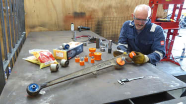
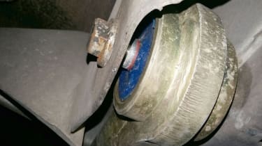
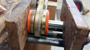
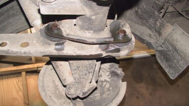
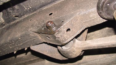
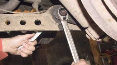
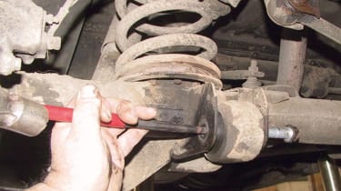
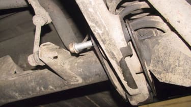
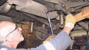
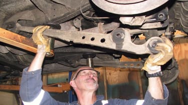
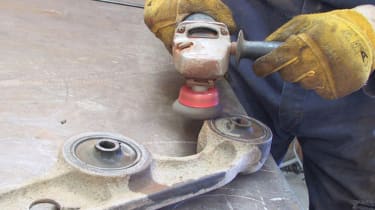
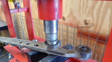
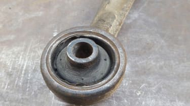
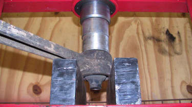
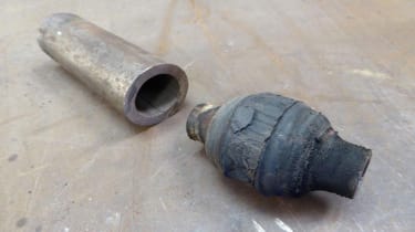
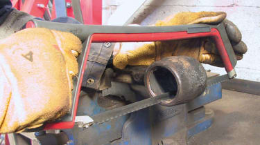
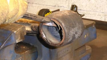
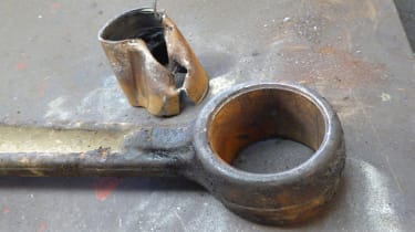
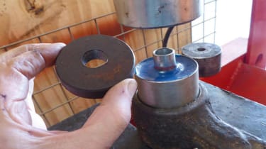
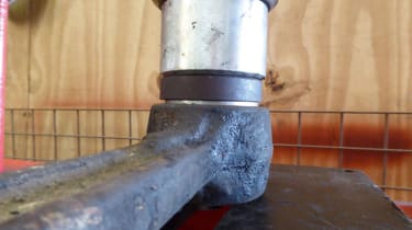
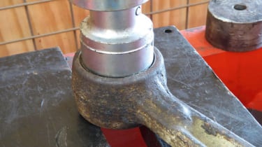
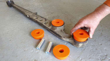
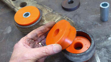
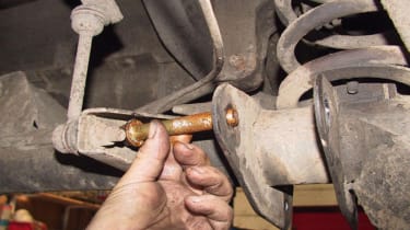
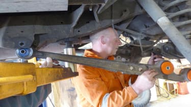
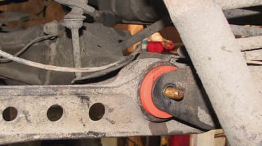
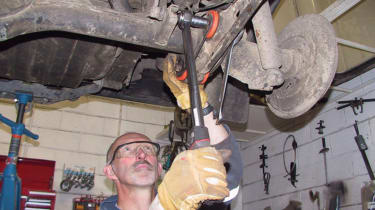
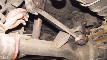
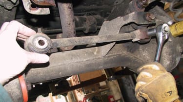
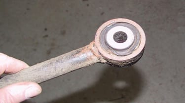
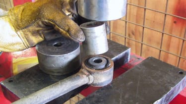
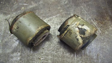
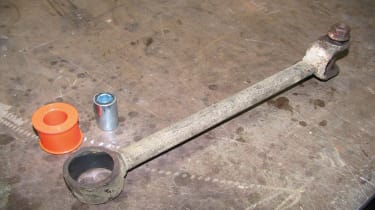
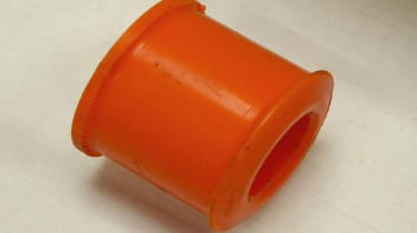
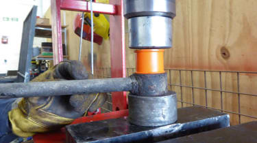
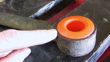
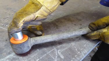
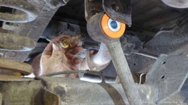
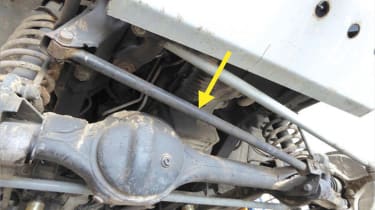
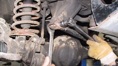
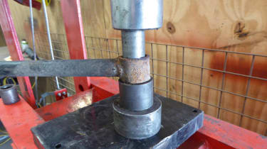
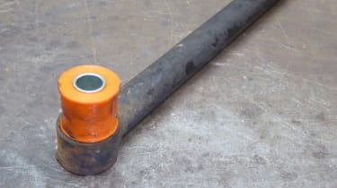
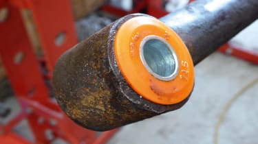
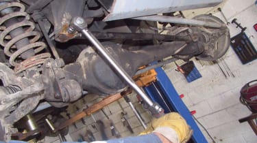
How to fit polybushes - pictures

Recommended
Land Rover Freelander on track for a comeback, but the UK will have to wait
Land Rover Freelander on track for a comeback, but the UK will have to wait
The Freelander name will be used for new range of electric cars, initially just sold in China but possibly coming here as well down the road
Land Rover Defender drives JLR profits to a ten year high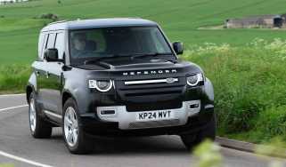
Land Rover Defender drives JLR profits to a ten year high
JLR prepares for a busy year ahead with the launch of the first electric Range Rover, and the next stages of Jaguar’s rebirth
Classic Land Rovers get all-electric power thanks to Inverted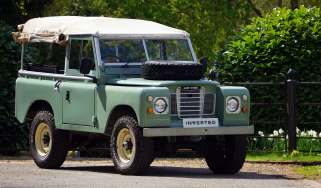
Classic Land Rovers get all-electric power thanks to Inverted
Inverted has expanded its operation to include Land Rover’s most iconic car
Best new cars coming soon: all the big new car launches due in 2025, 2026 and beyond
Best new cars coming soon: all the big new car launches due in 2025, 2026 and beyond
These are the most important new cars headed our way, from brands including Audi, BMW, Dacia, Ferrari, Ford, Skoda and more
Most Popular
Avoid using car finance claim firms, says financial watchdog
Avoid using car finance claim firms, says financial watchdog
FCA warns that using a claim firm could see consumers lose up to 30 per cent of their winnings if car finance redress scheme is implemented
Omoda 9 review
Omoda 9 review
Chinese brand’s flagship aims to offer premium-SUV kit and comfort, for the price of mainstream rivals. Can it deliver?
Best mid-size SUVs to buy 2025 - our expert pick of the top options
Best mid-size SUVs to buy 2025 - our expert pick of the top options
Mid-size SUVs are hugely popular in the UK, and these are the very best of the current crop