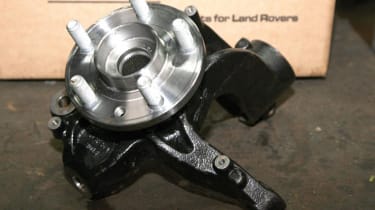
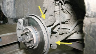
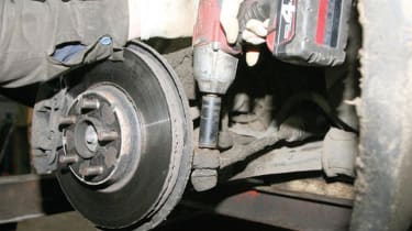
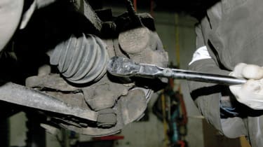
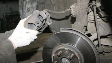
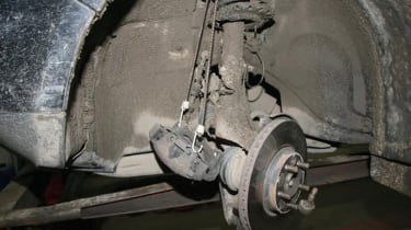
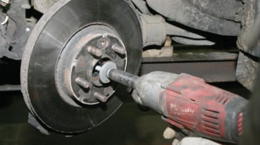
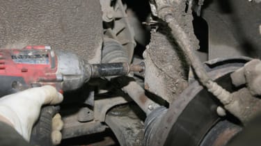
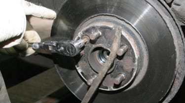
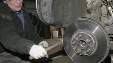
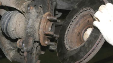
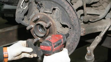
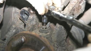
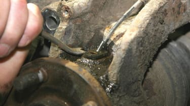
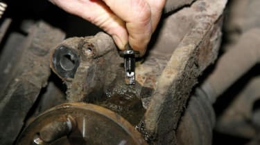
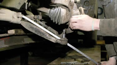
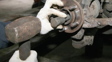
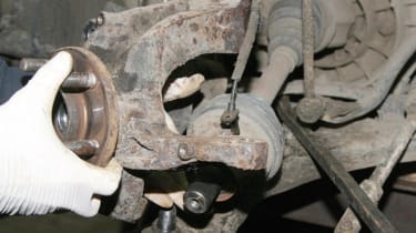
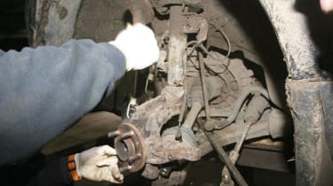
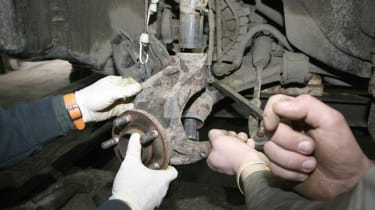
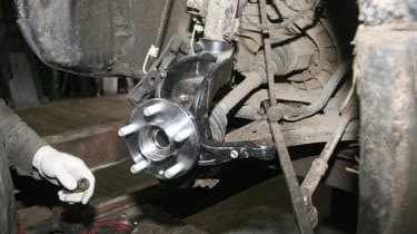
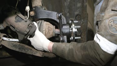
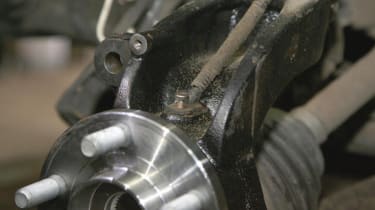
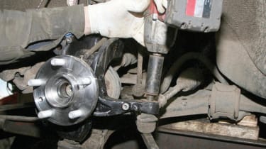
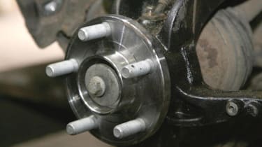
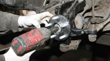
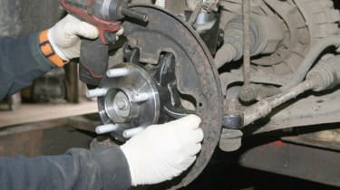
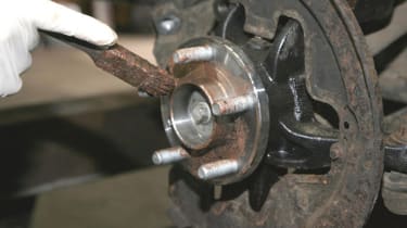
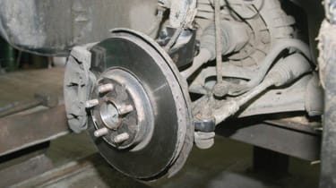
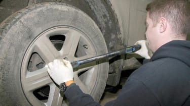
How to replace the wheel bearings on a Freelander 2 - pictures

<span>Front wheel hub bearing and steering knuckle assembly is part number DA1214, and a new driveshaft retainer bolt is part number LR000577</span>

<span>The wheel bearing is contained in the wheel steering knuckle, which is secured onto the MacPherson strut and lower arm.</span>
- Skip advertAdvertisement - Gallery continues below

<span>The ball joint nut securing the steering rack tie-rod to the wheel knuckle is undone and removed, and the rod released using a ball joint splitter.</span>

<span>Working at the back of the hub assembly, the securing bolts that are holding the brake caliper assembly to the wheel knuckle are released.</span>
- Skip advertAdvertisement - Gallery continues below

<span>The brake caliper’s two securing bolts are removed and the complete brake caliper assembly lifted off from the brake disc.</span>

<span>Once removed, the brake caliper assembly is secured clear of the wheel knuckle so as to not strain the brake hose.</span>
- Skip advertAdvertisement - Gallery continues below

<span>The driveshaft retainer bolt securing the driveshaft end to the wheel hub is removed and discarded, as a new one should be fitted during assembly.</span>

<span>The clamp bolt securing the wheel knuckle top onto the left hand MacPherson strut is undone. More often than not this is seized.</span>
- Skip advertAdvertisement - Gallery continues below

<span>The brake disc single retaining screw that holds the brake disc in position onto the front hub assembly is removed.</span>

<span>If the brake disc is seized onto the hub assembly, it is removed from the hub using a soft-faced hammer. Light force may be required.</span>
- Skip advertAdvertisement - Gallery continues below

<span>Once the disc is removed we could see that corrosion had rusted the inside of the brake disc onto the hub assembly.s</span>

<span>The three screws that are securing the brake disc shield onto the wheel knuckle are removed, then the brake shield is lifted off.</span>
- Skip advertAdvertisement - Gallery continues below

<span>With care, as the Torx bolt is easily snapped, the securing bolt holding the ABS/speed sensor into the wheel knuckle is undone and removed</span>

<span>Again with care, as its easily damaged, a pry bar eases the ABS/speed sensor out from the top of the wheel knuckle.</span>
- Skip advertAdvertisement - Gallery continues below

<span>Once removed from the wheel knuckle, the sensor is carefully moved clear of the work to avoid it becoming damaged.</span>

<span>The securing nut holding the suspension lower control arm onto the wheel knuckle is removed, and then the ball joint can be split.</span>
- Skip advertAdvertisement - Gallery continues below

<span>Using a suitable soft punch, the driveshaft is then knocked back through the front hub assembly and the wheel knuckle.</span>

<span>When the drive shaft has been knocked back, the wheel knuckle can be pulled outward, moving it clear of the driveshaft.</span>
- Skip advertAdvertisement - Gallery continues below

<span>With the driveshaft removed from the hub/wheel knuckle assembly, it is knocked downward off the MacPherson strut.</span>

<span>With the help of a pry bar, the complete wheel knuckle and hub assembly can now be removed from the vehicle.</span>
- Skip advertAdvertisement - Gallery continues below

<span>Now, the new wheel hub bearing and knuckle assembly is fitted into position on the MacPherson strut and the clamp bolt refitted.</span>

<span>With the wheel hub bearing and knuckle assembly in position, the driveshaft can be slid back into the new hub and the lower arm refitted.</span>
- Skip advertAdvertisement - Gallery continues below

<span>With the driveshaft now in position the ABS/speed sensor is fitted into the hub assembly, and the retaining bolt fitted.</span>

<span>The steering tie-rod end ball joint is fitted into the wheel knuckle, and the ball joint securing nut is fitted and tightened.</span>
- Skip advertAdvertisement - Gallery continues below

<span>A new driveshaft retainer bolt is screwed into the end of the driveshaft. It is recommended that a new bolt is used every time.</span>

<span>The driveshaft bolt is tightened to the correct torque setting. This process pulls the shaft fully into position in the hub.</span>
- Skip advertAdvertisement - Gallery continues below

<span>The brake disc shield is refitted and the three retaining screws tightened. The shield prevents brake dust from spreading and keeps dirt off the disc.</span>

<span>Before refitting the brake disc, some anti-seize grease is applied to the hub to prevent the disc seizing onto the hub again.</span>
- Skip advertAdvertisement - Gallery continues below

<span>The brake disc and caliper are refitted, tightening all bolts to the specified torque. At this stage, all bolts are re-checked for tightness.</span>

<span>With the job now completed, the road wheel is refitted, and the wheel nuts tightened to the correct torque setting.</span>
- Skip advertAdvertisement - Gallery continues below
Most Popular

Who needs hybrids? Diesel Skoda breaks world record with 1,759 miles on one tank

New Jaguar GT shows off more of its controversial and crucial design

Car Deal of the Day: Jaecoo E5 EV brings premium SUV attitude for a compact £243 a month